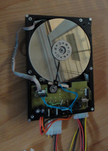
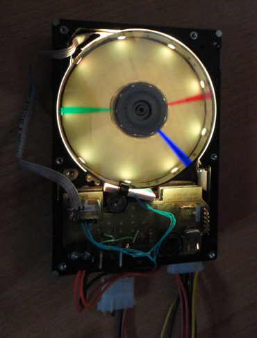
What exactly is a Harddrive Clock? It's an old Harddrive from a computer, with a slot cut in its' platter. There's also a light under the platter. When the harddrive spins, the color and intendity of the light, is adjusted in time with the location of the slot, by a microcontroller. To the viewer, the platter seems to disappear, and only the colored light remains, hovering above the surface of the harddrive's metal case where the platter was located. The result is what appears to be the translucent image of the hands of a clock moving where a silver platter used to be. It's a nice effect, which relies on "persistence of vision" just like an older CRT Television uses as it draws an entire picture with nothing more than an electron beam 'dot'. Only this system uses a rotating slot instead.
The drawback is noise. The harddrive spins the platter using its' own internal logic, so it's spinning around at 7200rpm (in my case), and the slot creates enough disturbance in airflow, to be quite noticable.
The position of the platter can be determined a few ways. A tiny magnet on the underside of the platter, and a hall-effect sensor on the logic board to detect the magnet as it goes by. Or, a simple IR LED on one side of the platter, and an IR sensor on the other side. I chose the IR solution, because I had just such a sensor kicking around from some device I had previously ripped apart. If you choose the hall-effect sensor, you need to choose a part that can make decisions VERY quickly. There are a lot of hall-effect sensors out there that are no good for anything except sensing the opening and closing of a clam-shell shaped cellphone. They include a lot of hysteresis and debouncing logic, which totally work against you when you want to detect 7200 hits per second.
The microcontroller logic turned out to be simpler than I expected. You setup one of the internal timers to run at a high speed, possibly even counting CPU cycles. Free-running mode. Whenever your sensor detects the slot go by, examine the current value of the timer, and then immediately zero it again for the next pass. Divide the value of the timer that you observed, by some constant such as 60. That would give you 60 segments around the clock face. Now, as the timer continues to increment on its' own, you are watching for each multiple of that divided timer value, to know exactly when to change the color of the LED's. There is only one color being output at any time. The entire string of LED's are outputting the same color at any particular moment in time. It's only the position of the slot that affects what color you can see, and where (that's the persistence of vision part of it). Because the code uses the timing of the previous rotation as it renders the next rotation, it produces a perfectly stable image. It's surprisingly stable even if you apply your finger to the platter. Slowing the platter too much, can cause the image to distort, since the timer will overflow before the rotation completes. You can fight this, by slowing the counting rate of the timer.
The code for this project turned out to be some of the smallest code I've written for a microcontroller project.