|
|
|
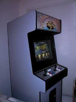
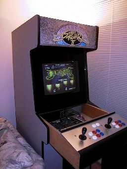
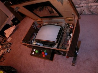
This upright arcade machine was purchased for $150 Canadian at the 1999 Arcade Auction held in Vancouver BC. It has no artwork whatsoever on it (meaning I can put whatever artwork I desire on it in the future). The surface of the cabinet is in perfect condition -- not a scratch. It looks like the cabinet was originally a "Street Fighter II Championship", and was converted to "Street Fighter 2 Hyper" sometime before the sale. Since taking the photo, I have converted it to a (50-PIN JAMMA-like) standard which I convert all my games and cabinets to use (see below). Because the power switch is at the back of the machine, I needed an easier way to turn it on. I recenly added a small switch-box inside the drawer which contains an ON switch, Coin switch, and Service switch. The cabinet itself has 1P/2P start buttons, two controllers, and 6 buttons per controller (plenty for running any game I have). It has a 19' monitor which is easily rotatable for both vertical and horizontal games. Access to the monitor adjustments and power supply are through the back of the machine. Rotating the monitor is performed (easily) by unlocking and pulling forward the controllers (2nd photo above), and then removing the front glass, and 4 bolts holding the monitor in place. Access to the PCB and controller wiring is through the front. After opening the coin door, a lock can be found which allows the controllers to be pulled out like a drawer. The PCB sits in there. The controllers can be unlocked and folded down for working on as well. The marquee needs a good replacement too. The one that came in it was not only badly centered, but also opaque. The machine itself is in perfect condition, and required only minor monitor adjustments once I got it home.
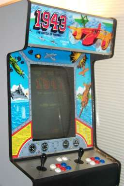 |
UPDATE: Here is the same machine, now sporting some very nice looking 1943 artwork! I still need to get my hands on either some 150dpi+ scans of 1943 side-art, or alternatively, the real thing! If you have 1943 sideart, and are willing to part with it, or willing to scan it, PLEASE contact me!!! It would be very nice to be able to complete this cabinet. rogermilne@shaw.ca |
 |
 |
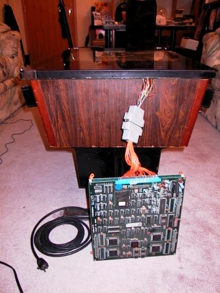 |
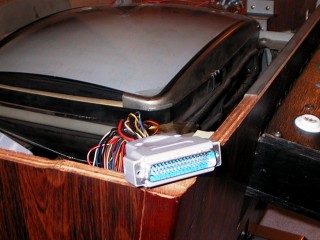
Here is a good photo of the custom plug I use in all my conversions. For any particular game, I build a wire harness that converts from that games' edge connector to a plug which will mate with the one shown top-left. Needless to say, some harnesses work for multiple games, such as the JAMMA harness. The pictures above are of my cocktail table with its' top open (like a clam-shell). I believe that the machine was originally a "Space Invaders" cabinet. That would also explain why the controller pods have been re-built (Space Invaders had onle a left/right joystick). The monitor in this machine is rotatable, and has adjustments easily accessed near the top of the cabinet. The cabinet itself has very little room inside, and most games I play on it I leave sitting beside the machine. It's easier access, and I don't have to worry about it accidentally touching the tube, or anything else bad in there. I have upgraded the audio in this machine as well, by adding a second speaker for stereo games. |
 |
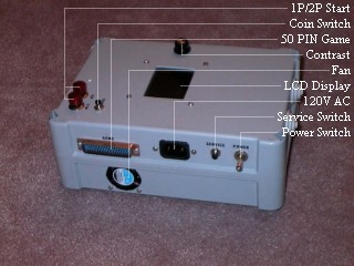 |
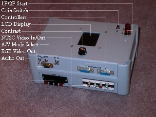
Above, you see the front and back of the unit. You can optionally plug it into a TV (or RGB monitor), or you can take advantage of the internal backlit LCD display and speaker, making it a completely self-contained arcade machine. The coin button, and 1P/2P Start buttons are mounted on the unit itself, while the controllers are on cables like a traditional console machine (like a PlayStation). The box itself which everything is mounted in was originally a water-tight box. After I drilled all those holes in it though, I wouldn't be so quick to call it water proof any more. The box itself measures 9.5" x 6.5", and is 4" tall. Not much larger than the power supply itself. Where'd the name come from? My friend, Chris Mair, bubbed it "The Lunchbox Arcade Machine" when he saw it the first time. The machine uses the same custom plug that all my machines and games use, making everything I own interchangable in seconds.
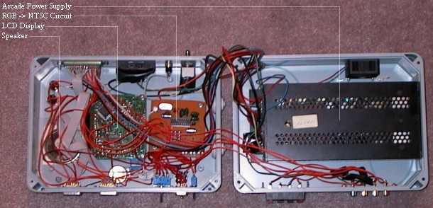 |
Here's a good photo of the internals of the device. It hilites the LCD display driver, an RGB->NTSC circuit used to drive the TV, or LCD display, the speaker, and the power supply. And a lot of wiring.
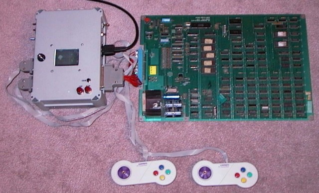 |
And here's the Lunchbox running Jr. PacMan (you can just make out the cloud from one of the title screens). The controllers are cheap Gravis Grip controllers ripped apart and re-wired to work as arcade controllers. This proved more difficult than I anticipated. There is *NO* spare space inside those things. The only trouble with the Lunchbox is that the games are bigger than it! People have asked about running it off batteries. It could be done, but these old arcade games suck so much current, the batteries would last only seconds. Maby it could be adapted for use with a car battery :-)
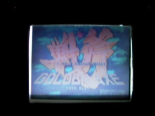 |
...And this is Golden Axe running on the Lunchbox. It's very difficult (at least with THIS digital camera) to get a good photo. That's the best I've been able to get so far. It's a backlit screen, measuring about 2.5" x 2". I estimate the resolution at about 160x120 pixels. (lower than I had hoped for, but still perfectly recognisable). Some fonts (especially 8x8 pixel fonts) can be hard to read. My C64, when displayed on it, was hard to read. The LCD display does do an *excellent* job at color-matching the RGB signal. |
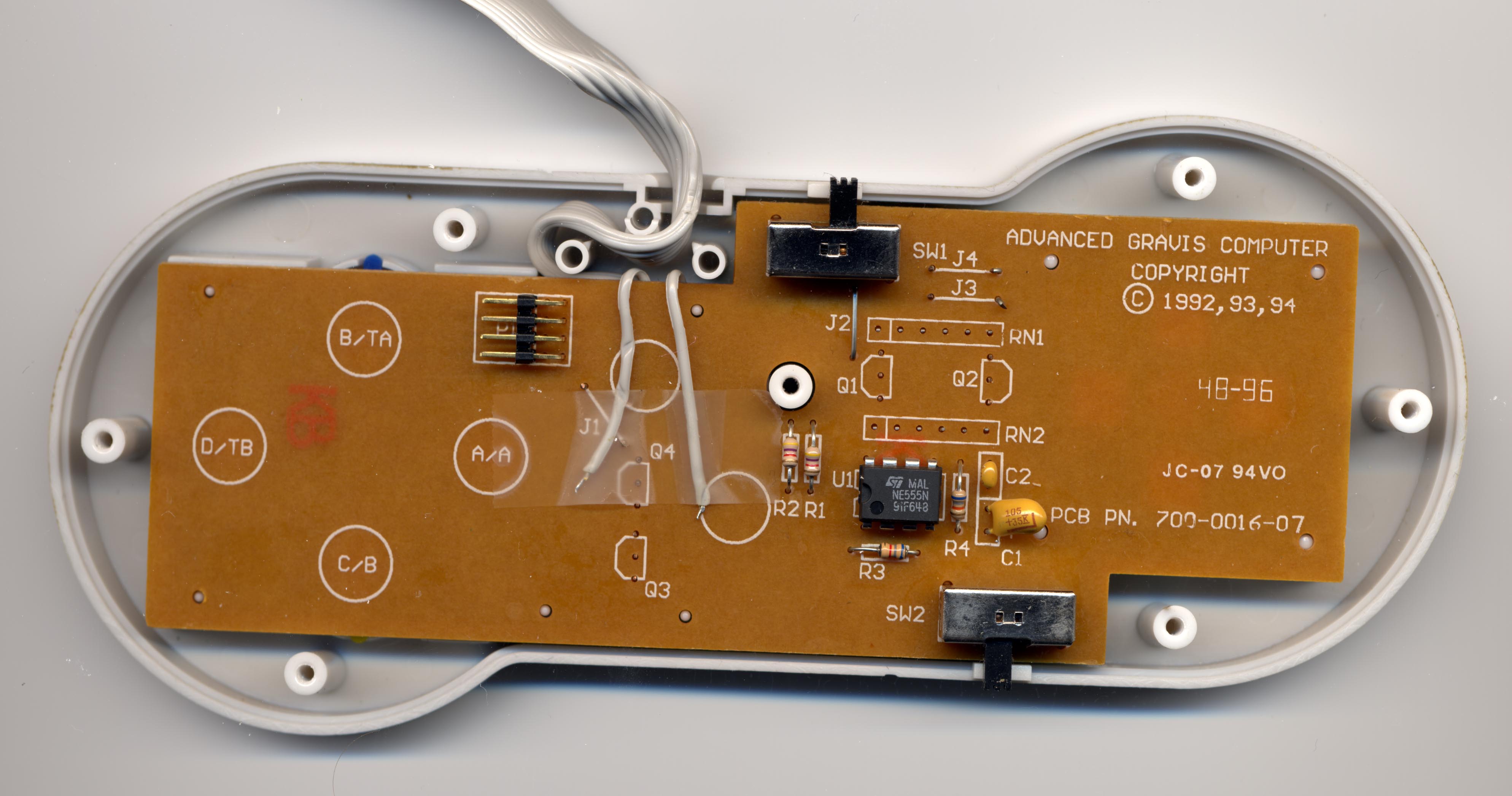
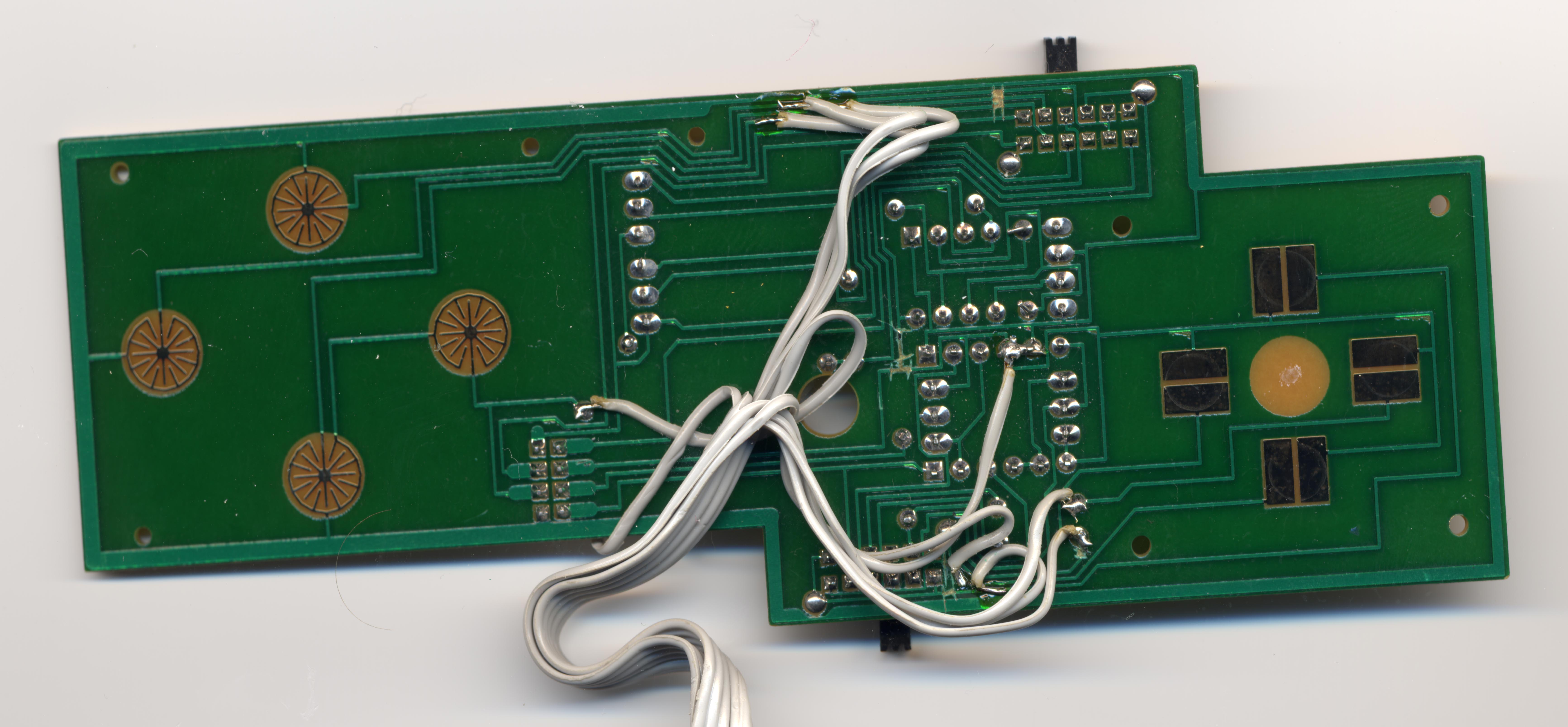
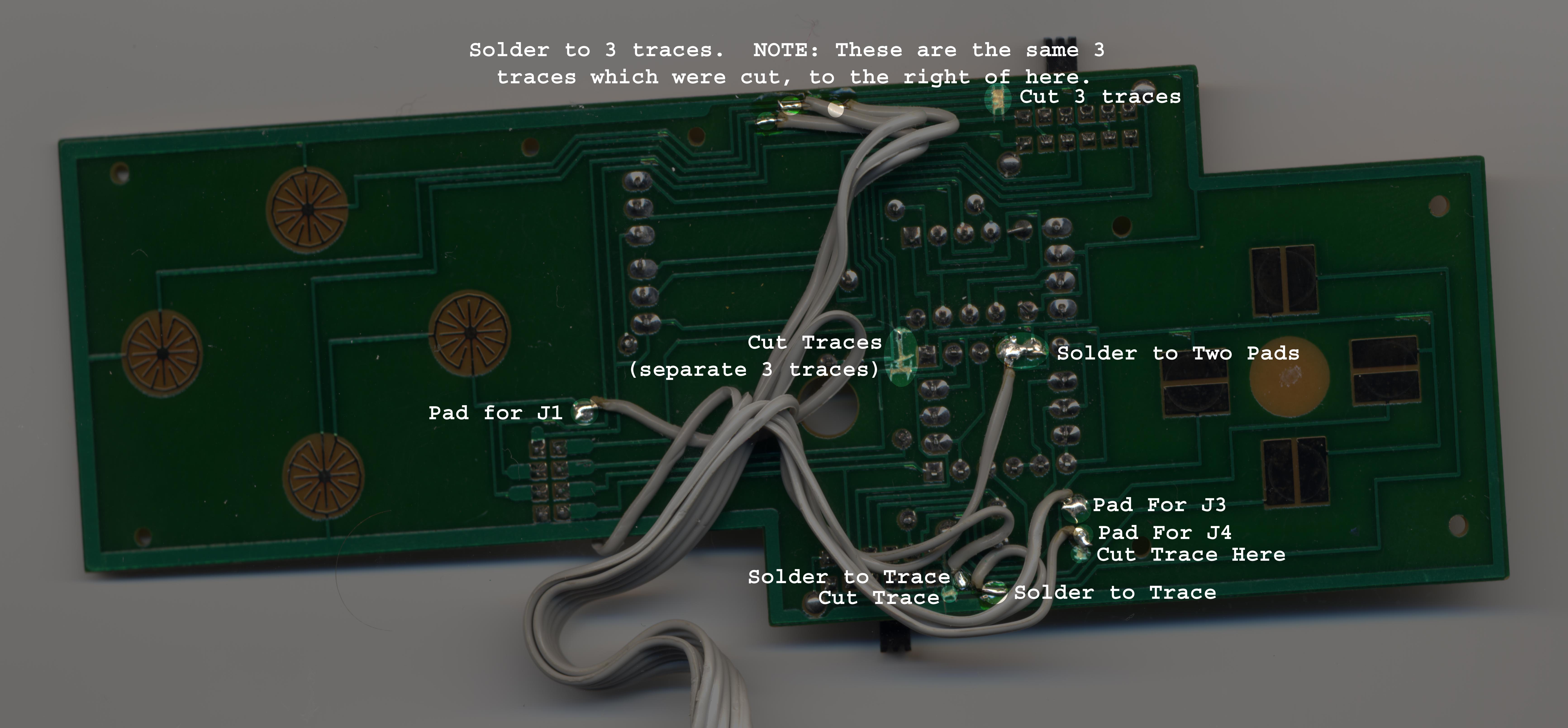
The Gamepads are modified "Gravis PC Gamepad" controllers. I modified them rather drastically. First off, here's a few scans: PCB TOP, PCB BOTTOM (unedited scan), PCB BOTTOM (showing solder points), PCB BOTTOM (showing signal names).
The inside of the Gamepad is VERY cramped. I used a ribbon-cable for my wire. The wires you will need to solder between your JAMMA connector and your Gamepad are: Ground, Button1 through Button4, Up, Down, Left, and Right. As seen in the first scan, you will need to cut several traces on the PCB. This is done to isolate some of the more complex parts of the Gamepad circuitry, which would otherwise interfere with the rather simple "arcade machine" logic we need. We also need to remove several of the components, leaving a rather lobotomized PCB. (RN1, RN2, Q1, Q2, Q3, Q4, J1, J3 and J4 are all removed). Note that the two wires taped to the board in the first scan are just extra wires I left on the ribbon cable, for future expansion (coin, and start buttons). At this time, they are not connected to anything. Next, examine the remaining scans. The wires are all twisted funny because they are being routed around the various posts inside the Gamepad's plastic case. Also note that the two switches are no longer functional. The wires which are soldered directly to traces can only be soldered after you have carefully scraped the green paint off the trace, exposing the copper itself. Use a paint program so you can zoom into the scans to see exactly where I soldered, since some of the traces are difficult to make out. Good luck making your own gamepads!!! I wrote these instructions about a year after actually making the joysticks themselves, so the information I can provide about what I did is rather limited :-( If you have specific questions or can't make something out well enough, please write me. Considering the complexity of the project, I expect you have some sort of electronics background (even just hobbiest) if you take this on.