Playing Trackball games on your Joystick Machine
Ever wanted to play your Trackball or Spinner based arcade game boards in your
generic (joystick-based) arcade cabinet?
Well, here's a design for a small circuit which will convert joystick
data to trackball data for games such as Cabal, Centipede, Rampart, Arkanoid, etc.
Contents
- Overview of operation
- Description of the circuit design
- Circuit Parts
Build at your own risk!
I will not be held responsible for anything that happens to your games
if you build this.
Overview of operation
Here's the problem:
Joysticks report data like this to a game: UP, DOWN, LEFT, or RIGHT.
When you roll a Trackball to the right, the game sees this: 0,1,3,2,0,1,3,2,0,1,3,2 (spinning the trackball faster makes the number sequence happen faster)
So, the task is to convert a direction from the joystick, like RIGHT, to a stream of numbers as if generated by the trackball.
To do this, you'll need a source of pulses, a counter to count those pulses and generate the numbers, and some logic to control which way the numbers count (reverse the order of the numbers to reverse the direction).
One remaining task is to allow one of the players' buttons to control how fast to
move (a trackball gives you a LOT of control over this. My circuit will give you
a choice of two speeds: Slow, or Fast). Basically, hold a button to move fast.
This is the same sort of control method the joystick version of "Rampart" uses,
and doesn't take too long to get used to.
Description of the circuit design
I have split this design into 4 specific parts. You can build each one on a different
board if you want, or you could build it all on the same board, whatever you wish.
- Clock Generation
- You will need only one Clock Generator circuit. It will drive all other circuits.
- Joystick Data Preperation
- You will need one Joystick Data Preparation circuit for each player.
- Speed Control
- You will need only one Speed Control circuit to drive all other circuits.
- Axis Processor and Output
- You will need *TWO* Axis Processor And Output circuits for each player to reproduce a trackball.
Alternatively, to reproduce a spinner (like Arkanoid), you'll only need one of these.
Basic Clock Generation
First thing's first: Lets get a source of clock pulses that everything else can use.
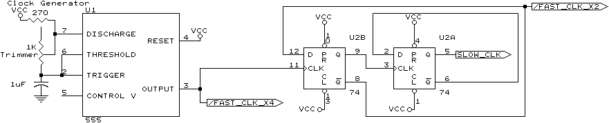
You'll need to build one of these circuits. It will drive as many players'
controllers as you need. It has a trimmer-pot which allows you to choose the
over-all speed which the trackball appears to be spinning. I used a multi-turn trimmer,
which simply means it has very fine control (it can be turned in a full circle about 50 times
to go from one extreme to the other). One end of the trimmer is not connected to anything.
This circuit is based on the popular 555 Timer chip. It generates pulses at a specific rate.
These pulses are then divided by two by U2B and then once more by U2A. We now have all the
clocks we need to get everything done.
This one circuit will drive all other circuits. Built it only once.
NOTE: If you are unable to tune the circuit to the desired speed, replace the 1uF
capacitor with a larger one to slow things down, or a smaller one to speed things up. (try a 0.1uF or 10uF capacitor as necessary, or fiddle until it's the right speed)
NOTE: The signals inside arrows are sent to other circuits (connect wires from this board
to other boards as necessary).
Remember, this is a schematic. POWER and GND are not shown!!! You will
need to connect +5V and GND too. Steal +5 and GND from the cabinets'
power supply (*NOT* the transformer, the black box that feeds your game!!!).
- VCC (+5V)
- U1 (555) Pin 8.
- U2 (7474) Pin 14.
- GND
- U1 (555) Pin 1.
- U2 (7474) Pin 7.
Next, lets put a jumper on the board. This jumper will let you choose how much faster the FAST button goes.
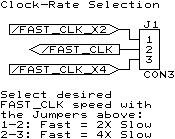
This Jumper is simply 3 posts sticking up like on your typical PC motherboard. You then stradle two pins with a
black jumper. Alternatively, you could use a DTSP (two-position, aka "ON-ON") switch. Put the jumper on NOW
(in-case you forget later) or your FAST button will make everything stop, instead of making things faster.
Joystick Data Preperation
Ok, now lets prepare some joystick data for use by the circuit.
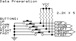
The idea here is: TTL chips (anything starting with 74) requires information to be +5 or GND to create a 1 or 0.
This circuit converts the arcade machines' switches into 1 / 0 selectors for the TTL chips to use.
Your cabinet may already have one side of your switches tied to GND. You'll probably only have to add
the resistors to +5V. Don't put these resistors directly on the switches, unless you're making this
trackball-to-joystick conversion permanent in your cabinet.
You'll want to build one of these for each player (it takes the wires from your joystick in, and puts resistors
to +5V on them, then passes the information on to the other circuits). You can steal the +5V from the
Clock Generator board you have just built.
Speed Control
Now, it's time to implement the FAST button.
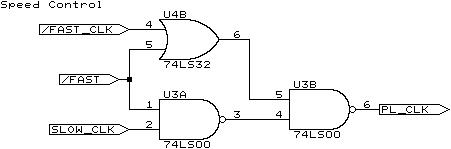
This circuit will allow the FAST button for a particular player to choose one of two clock sources - fast or slow.
If the player is holding the FAST button down, this circuit chooses the /FAST_CLK from the center-pin of the jumper/switch above.
If the player has released the FAST button, this circuit chooses the SLOW_CLK from the Clock Generator circuit.
Whatever the selection, it is passed-on to the Axis Control circuits (below).
You will need to build one of these for each player.
Don't forget these!
- VCC (+5V)
- U3 (74LS00) Pin 14.
- U4 (74LS32) Pin 14.
- GND
- U3 (74LS00) Pin 7.
- U4 (74LS32) Pin 7.
Axis Processor and Output
And finally, the heart of the project. The Axis Processor knows how to put everything together and make "fake" trackball data for your game.
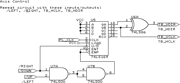
Wow, you're on the home-stretch. This circuit takes one Axis (horizontal, or Vertical), and converts it to trackball data. If you are replacing a spinner,
you'll only need the one axis (horizontal, probably). If you're replacing a trackball, you'll need to build two of these
(and use the alternate names above or below the arrows for the second copy).
U7A detects whether up or down is being pressed by the player. U7B then prepares the information for the counter. U5 (the counter) counts the PL_CLK
information from the appropriate Speed Control circuit for this player. U6A converts the output of the counter (0,1,2,3) into trackball data (0,1,3,2).
NOTE: If your circuit is making things move backwards on this axis, you can move the wire on U5 pin-1, from pin 1 to pin 2 on U7A to reverse the direction.
And again, don't forget these!
- VCC (+5V)
- U5 (74LS169) Pin 16.
- U6 (74LS86) Pin 14.
- U7 (74LS00) Pin 14.
- GND
- U5 (74LS169) Pin 8.
- U6 (74LS86) Pin 7.
- U7 (74LS00) Pin 7.
Images
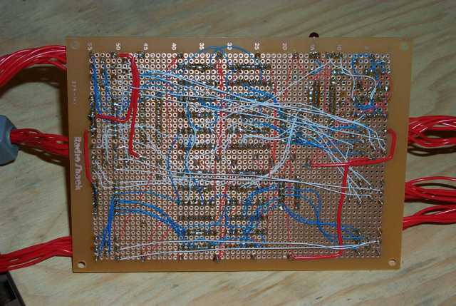
Here are a few images of my completed circuit. It differs from the design I show here only in that
I built 3 copies of the device all on one board. And because I did that, I chose
to take advantage of spare gates on chips which were not completely used. This saved me a total of
two chips (if I recall correctly). Other than that, the circuit is identical to what I describe above.
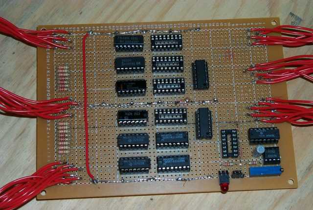
You'll probably notice I do not have enough chips to run all 3 players simultaneously. The remaining
chips are on order. (The row with the missing chips contains all the counters. I can move the
existing two counter chips to the other slots and check the other players, but I can not run all 3
players simultaneously). In the bottom-right corner, you can see a long-skinny blue object. This is
the trimmer-pot. left of that is the jumper, and left of that is a power LED. To add one of those,
tie one end of a LED to GND, and send the other end of the LED through a 22 ohm resistor to +5V. If
the LED does not light up when power is applied, reverse the LED. The three silver lines running the
length of the PCB are power rails. The outer rails are +5V, and the center rail is GND. There is one
final empty chip socket near the trimmer-pot is not used. I just didn't bother to remove it.
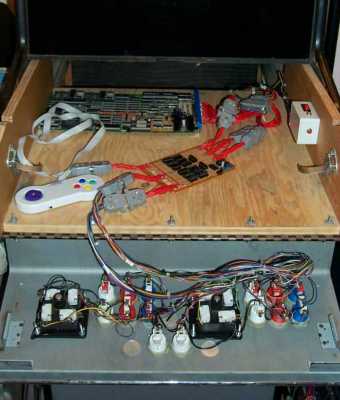
This is facing the front of my arcade machine, with the control-pannel folded down (open). Players 1
and 2 use the built-in controllers, but if a 3rd player wishes to play, I have modified a Gravis Gamepad
for him. The PCB in the background is "Rampart". Notice all the connectors are the same standard as my
other machines
(Cocktail Table and Lunchbox).
Home Page
Email rogermilne@shaw.ca for questions, etc.