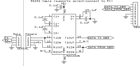
This is a microcontroller project. My inspiration was from a similar project I'd seen on the net, but they shared very little information, just a general description of what they were doing. So I felt that I just had to make my own and then share the knowledge :-) This is not a complete how-to, but hopefully it has more than enough information for someone else to enjoy building a device like this.
The game involves players spinning the platter of the harddrive as fast as they can, using whatever method they see fit, so long as it's their finger that ultimately spins the platter (not a dremmel-tool, for example ;-) It may not sound too exciting to some, but it's been well proven at my work that it's a highly addictive game. They give it one half-ass spin and see 500 RPM, and see just how astronomically far off they are from the high-score, and that leads to two spins, and then 3, and they're up to maybe 1000 RPM and trying hard, and then the wonderment kicks in, of how in the world the 1st place person achieved 2339 RPM :-) Several people have played it to the point of inflicting self injury. Calluses build on the digits, sprained fingers, and blood has even been drawn. Oh, the fun we've had...
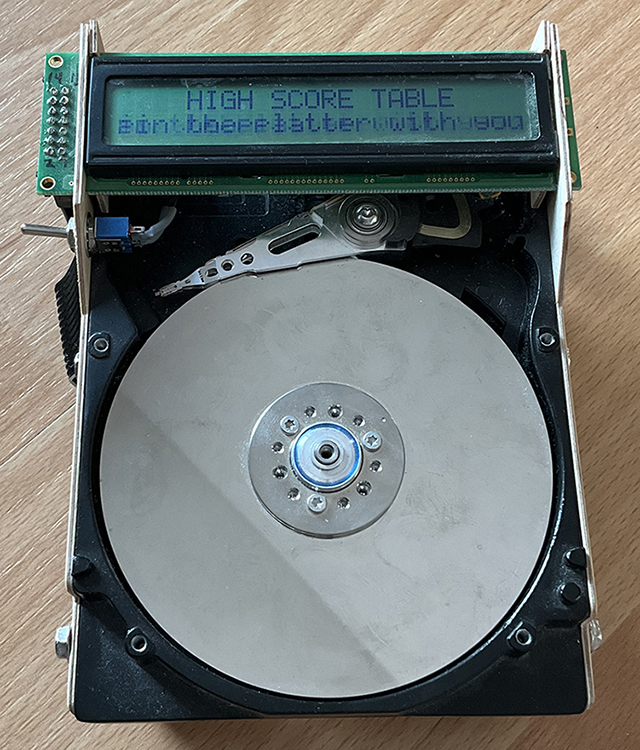
The game will show (real-time), the current RPM of the platter. It will also show your current 'Best RPM'. You may continue to make additional attempts, until your finger is sufficiently sore. At this point, a small inactivity time-out will fire, and the game will grant you a high-score position if you so deserve it. If not, then the game will return to the waiting-for-a-player state (where it scrolls through the current high-score table). The machine will remember (internal EEPROM), the high-score table, even when the power is removed.
Should you be good enough to achieve a high-score, the machine will allow you to input your name. You can rotate the platter left or right, to scroll through a list of letters. When you stop on a letter, some arrows will approach from either side of the screen. Moving the platter again, resets the arrows. If the arrows are allowed to meet at the chosen letter in the middle, then that letter is entered into your name. A backspace feature is also provided.
The machine is extremely sensitive to the platter's rotation, and you can easily rotate the platter very slowly to advance one single letter. It will detect as low as about 70RPM, meaning approximately 1 rotation per second. It can also detect the direction of rotation.
The basic premise is that a typical IDE harddrive contains a 3-phase (brushless) motor. The platter is rotated, by applying power in a cyclic manner, to the 3 coils (phases). By changing the timing of the energizing of the coils, you can control the speed of the motor. Very important for a harddrive which is supposed to spin at, for example, an exact 7200RPM.
As the motor turns, its' own motor magnets pass by the motors' coils, and a tiny Back-EMF surge occurs. This Back-EMF can be measured by a microcontroller, and in a normal harddrive, the timing of it is used for making the decision as to whether the platter needs to accelerate or decelerate in order to stay at the intended RPM (eg. 7200RPM).
In this project, we'll rip all the existing harddrive electronics out, and hook directly to the motor's 3-phase wires ourselves (for the sole purpose of listening to the Back-EMF). By listening to one of the phases, we can tell how fast the platter is turning. By listening to TWO of the phases, we can tell both the speed and direction that the motor is turning! A microcontroller can compute the time between each Back-EMF pulse, and use the spacing between the phases to compute both the RPM and direction of the platter!
[ARM-CHAIR PHYSICS ALERT: I wrote this as an interesting side-note.
Not to be totally accurate with respect to what's going on]
An interesting note regarding Back-EMF. It's a form of energy. It came from the interaction of a
magnet and a wire. The laws of physics state you can't get something from nothing. So what did
you loose when you created the voltage? You lost some rotational energy, or speed on the platter.
Try spinning an un-powered 3-phase motor that is not attached to any circuit. Then try shorting
all 3 motor wires together and spinning it again.
You will notice a fairly significant resistance to your attempts to spin it once you have shorted
the wires together. It will not spin freely anymore either, and will come to a stop much more quickly.
This is ABSOLUTELY a build-at-your-own-risk project. I make no guarantees whatsoever. I don't know whether you'll be able to build something that works either. This is a prototype device that I'm documenting here, and I may have errors in my documentation.
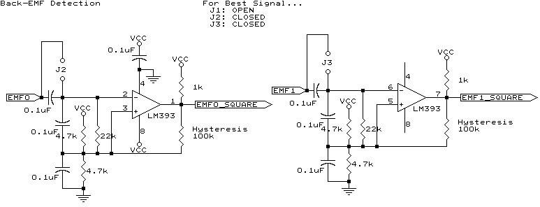
This is by-far, the most important, and most fiddly part of the project, so we'll start here. We need to detect pulses of emf that measure in the millivolts, if I remember correctly. Whatever it is, it's freaking SMALL. When you simply touch the 'scope lead with your finger, you inject more volts than we want to measure, here. The LM393 can do just what we need. Amplify that tiny pulse into something we can offer to the microcontroller. We need the super-sensitivity for when the player is spinning the platter very slowly, eg. when entering their name. Each time there's an EMF pulse, we want to reflect it in the output state of the LM393. That way, we produce a signal that is very similar in concept, to an encoder-wheel on an old mouse or track-ball.
Bread-board this circuit first, and make sure it's working for you before building the final board. I found it rather fiddly to get the sensitivity up without detecting things like 60Hz in the air, coming from my wall or lights, passing through my body, out my finger, through the platter, through the motor, and into my circuit. Drive it using a signal generator until it appears to work, then move on to the next step.
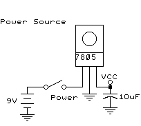
Powering the circuit, is a simple 7805.
After selecting your harddrive, you'll need to strip it down so that it contains only the platter, motor, and metal carrier (case without the top). I left the read/write heads in mine, but removed the breaking mechanism and servo that control it, so the head is just sitting loose on its' spindle now.
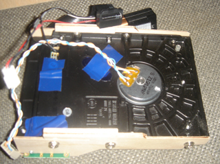


Once the circuit-board has been removed from the bottom of the drive, you'll likely see something similar to the photos above... You'll need to add the wires you see in the photo. BUT: they may not be in the same order for me as they will be for you. You should measure the resistance between all combinations of the 4 pads, as there should be a common ground-wire for all phases. You need to know which one it is. You can identify it because you'll see a lower resistance whenever it is involved in your measurement. If you have only 3 pads, then you have a harddrive with the wrong kind of motor windings (no common ground). This would be a problem. Go find another harddrive. (i don't even know if harddrives are made like that, but I know 3-phase motors can be built like that). Wondering which harddrive I used? I think it was a Western Digital, probably somewhere around 250 to 500 megs. It has only a single platter, and a top and bottom head.
Note the 10uf capacitor in the above schematic. When the harddrive is attached to the detection circuit, this capacitor is what isolated my finger (and thus me, the giant antenna), from the detection circuit, allowing it to see the pulses and not the 60hz crap in the air around me, when at low RPM's. If you want to adjust sensitivity of the circuit, the 100K hysteresis resistors in the detection circuit can be adjusted, to control how sensitive the circuit is.
Once the motor wire has been soldered on, you should be able to 'scope motor wires 3 and 4 as signals, while using motor wire 1 as the common-ground. Leave J1 open (no jumper is needed here). However, if you've gone so far as to connect the motor to the above detection circuit, then you'll need to install jumpers on J2 and J3 before the square-wave will output correctly. Just watch one of the signals for now. Give the platter a spin, and you should see the following...
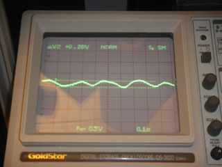
Above, you see the Back-EMF signal from one of the motor wires when the platter is spun very slowly. So slowly, you can see the imperfections of my fingers' velocity in the shape of the sine-wave. We're looking at 1/4 of a volt here.
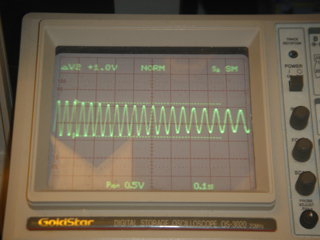
Without changing the scale of the display, I then spun the platter more quickly. The frequency of the back-emf has increased, as has the intensity of it (voltage). You can see the platter decelerating, too.
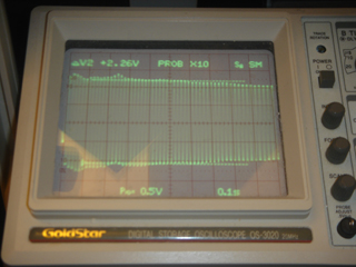
Finally, I give the platter a very fast spin, and you see that the trend continues. We're up to 2.25 volts now! I'm thinking this was about 600 RPM.
In order to compute the RPM, I'm not interested in the voltage, I'm interested in the frequency.
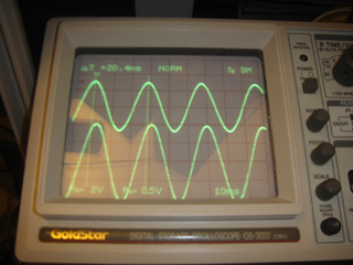
Notice, when both signals are displayed together, that there is a phase difference between them. This is what we'll use when detecting the direction of rotation.
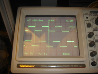
Now, 'scope the EMF0_SQUARE and EMF1_SQUARE pins of the LM393, and you should see the above output. I think I spun the motor in the other direction as compared with the previous photo, since the phase is shifted in the other direction.
At this point, things get much more complicated if you don't know PIC microcontrollers. Either you know what you're doing, or you don't, and I won't be able to explain it to you. Here we go...
The code is available for download here. Not all of this code was written by me. There are linker scripts, and a generic floating-point math library, both written by microchip and freely available elsewhere on the net.
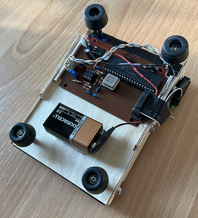
I used 3-ply plywood to frame the device, and hold the LCD, circuit-board, battery, and power switch in place. I hid the circuit-board and battery under the device. I used rubber feet attached to stand-off's, for a sturdy base which also provided clearance for the battery, so people could really wail on the platter and not have the device sliding around the table at the same time. All wood and parts are held in place by interlocking with eachother. There are only 3 screws on each side, in the standard harddrive-mounting holes, holding it all together. The battery is simply velcro'd in place.
Calibration is actually very streight-forward. It's more of a verification than a calibration. You use an RPM measuring device (which usually works with reflected light), and a piece of tape on the platter, to break the beam. Spin the platter, and check the meter. They should either be extremely close in value, or possibly be off by a factor of 2. Depending how the windings work inside the motor, you may find a factor-of-two difference between reality and the games' result. If this occurs, you'll need to dive into the code and make a tweak to divide or multiply the final computed RPM by some constant. My RPM measuring device is from the local aircraft hobby store, intended for measuring the speed of an R/C aircraft's propeller.